 The wider the channel region, the better conductivity of a device will be. Where electronics enthusiasts find answers. The only reason the prebuilt mosfets have a timer feature is so you can fire 3 round bursts. The add on modules were something he was playing with for later like the hud in the eotech, he also did preliminary work on gps tracking, wireless access, shot counter, elevation assist. int relayState = 0; void setup() { when I say "high" I mean the 555 one shot is going to output 5 volts.
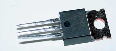
 int lastTriggerState = 0; Being part of the field-effect transistor family, it is a current-controlled device that is constructed with 3 terminals; The purpose of a MOSFET transistor is essentially to control voltage/current flow between the source and the drain. Thanks to this electronic circuit the battery energy is not lost while burning contacts but directed straight to the motor. The purchased MOSFETs often consists of two separate things: The MOSFET with the sole purpose to route the strong current directly from the battery to the motor but only let a smaller control current pass through the triggers, saving them from wear, debouncing them to some extent etc. Offering airsoft repair, upgrades, tuning and customization, check out: I dig the idea allot, it goes along with my long term idea I thought about having a means to make the trigger actually sprung with a sear rather than a switch like they are now. Thank you for taking a look. D1 is integrated into the controller for the gun so there is not much I can do to move that, but I think I will add your suggested protection just to be safe. In your prior post you put up a schematic -- it would be helpful if you made a schematic that calls out the Arduino, the battery input, the motor and MOSFET, and has a box (I would label it "magic") that goes between the Arduino output and the gate. The maximum speed is reached after 4 shots. If it's got two, then you need an ESC for a brushed motor; if it's got three, then you need an ESC for a brushless motor. I also would like the gun to function as normal when the Arduino is off, so I can use it as a normal AEG. Looks OK to me, I don't see anything that would need improvement. There are two classes of MOSFETS; Depletion Mode, and enhancement mode. although alot of things can take more then 5 volts as the input. Soil Moisture: Why Important, What Challenges, How to Measure & More, MiniFarm on reTerminal: Develop a Simple Farm Monitor & Water Management System. Due to the location of the switch it takes an appreciable amount of force to feed the bbs through. You'll need to work on the 200A part. They are just contain mosfets rated for high voltage. The Gate MERF 3.2 Mosfet Unit is the Third generation of airsoft Mosfets from Gate. In addition the IRF530 is only capable of 10-15A so not appropriate for the application. Mais ds que tout est prt je le fais ! My goal is to use an Arduino to detect and control the signal from the trigger to the gate of the MOSFET in the gun. I am a electrical engineering student that is nearly graduated. Thanks. I've also got a bb detect functionality that has not been properly tested. int cutoffState = 0; It would be helpful if I could also reverse the direction but I dont think thats possible with the currently components. Driving DC motor using a single MOSFET, why does the motor spin without applying a gate voltage? Sorry, I should of explained high and low, I dont expect anyone to know the electronics technical terms. Aprs il faut faire preuve d'ingniosit ! Soil Electrical Conductivity(EC): Whats It, Why Important, How to Measure & More, Metal oxide semiconductor field-effect transistor, 3 terminals: Gate, source, drain with higher structure complexity, For MOSFET to work, its dependent on the voltage at the oxide insulated gate electrode, For BJTs to work, its dependent on the current at the base terminal, A block, also known as a substrate of p-type semiconductor acts as the base for MOSFET, Two sides on this p-type substrate are made highly doped with an n-type impurity, The drain terminals (Source and Drain) are then brought out from these two end regions, The entire surface of the substrate is coated with a layer of silicon dioxide, A thin insulated metallic plate is then placed on top of the silicon dioxide, acting as a capacitor plate, The gate terminal is then brought out from the thin metallic plate, A DC circuit is then formed by connecting a voltage source between these two n-type regions, Depletion mode tends to be referred to as a normally closed switch, It states that when theres no voltage applied at the gate, channel conductance is at its maximum, When voltage is applied at the gate, The conductivity of the device decreases, Enhancement mode tends to be referred to as a normally open switch, where for conductance to occur, voltage is needed to pass-through, When theres no voltage applied at the gate, theres no conductance, When voltage is applied at the gate, the conductivity of the device increases, The drain and the source are doped with n+ impurity while the substrate is in p-type, The current flows through the P-channel MOSFET, When a positive voltage is applied on the gate, the electrons from the n+ source and the drain region are attracted towards it, forming an electron reach channel, Unlike the N-channel, the drain and the source are doped with p+ impurity while the substrate is in n-type, When a negative voltage is appleid on the gate, the electrons underneath the sulfur oxide respond to the flow of current and get pushed downwards into the substrate, Pairing with microcontroller to build a system that controls lights automatically through the respective clock pulses, Radio-controlled applications such as boats, helicopters, and drones, Industrial control environments and robotics, If youre looking to regulate the flow of high current in narrow pulses, or for any high power applications, MOSFET is the way to go, For common electrical circuit usages or low current in-home applications, BJTs may well be sufficient in handling the job, Two screw terminals on board; one for outer power source, while the other for the device you want control over with, Seeeduino is Seeeds very own Arduino board, built with relative benefits over the original, If you do not wish to purchase a Seeeduino, this tutorial is still applicable for the following Arduino boards: Arduino UNO, Arduino Mega, Arduino Leonardo, Arduino 101, Arduino Due, Step 1: Copy the code below into Arduino IDE and upload it, If youre unsure on how to upload the code, do check our guide. For a better experience, please enable JavaScript in your browser before proceeding. The gearbox had issues, and chewed up motors (The gearbox relied on the motor compressing the spring one last gear-tooth-worth). Thanks Vosem Media 8 mins ago, How do I drive a MOSFET when I have an 11.1v power-supply and an arduino [duplicate], Using Mosfet with seperate Logic Converter and Arduino, Design patterns for asynchronous API communication. Im currently working on a arduino controlled mosfet for my airsoftDMR. Do you just want to turn the motor on and off, or control its speed? The Gate MERF 3.2 package will includes everything you will need to get started: MOSFET: It eliminates any loss of energy which occurs while mechanical contacts touch each other. For the full in-depth introduction to MOSFET, do visit this page! Do you think the builtin protection on an Arduino nano's Vin are enough for this, or should I add something to help protect it? Maybe something like the uk.farnell.com/infineon/irl3713pbf/mosfet-n-30v-200a-to-220/dp/ maybe? If you know how to program in "C" then you can program a arduino. Building a MOSFET is very easy, there are a lot of blog pages/instructables available but you essentially connect trigger to Gate pin, battery to Source and the motor to Drain, plus a few resistors and a zener diode. As its name suggests, the Grove MOSFET is a miniaturized MOSFET transistor that helps you easily control a high voltage project with your Arduino board! Here's a suuuuper rough ms paint schematic: Ive been thinking about this and I realised that there is no need to worry about a cut off for semi since the gearbox already cuts off via the cutoff lever. rev2022.7.21.42639. It's already available. Below we have a MOSFET transistor recommendation, perfect for such usage! Was there a Russian safe haven city for politicians and scientists? I have seen many applications of the arduino as a P* FCU but is there anyway to use it as a traditional mosfet system? Other microcontrollers and single board computers. It only takes a minute to sign up. will require you to do some gearbox work and soldering but will allow you to take full advantage of the Features of this awesome Mosfet.
 } NUO 2022-03-21 PERSIKLME NAUJAS PATALPAS, FrSky D8RSP 2.4Ghz Receiver (w/telemetry). If you guys have any guidance that would be great! I have a cycle sensor cuttoff) that clicks everytime the gun cycles 1 time along with a trigger button and a relay to activate the mosfet. Was thinking about an Arduino based MOSFET last year, but didn't really start the project. This is about how to actually make the motor turn.
http://unconventional-airsoft.com/20rigger-master/, http://www.thefirearmblog.com/blog/2rduino-inside/, http://cooking-hacks.com/wp/wp-conte/10/switch.png. E.V. Stack Exchange network consists of 180 Q&A communities including Stack Overflow, the largest, most trusted online community for developers to learn, share their knowledge, and build their careers. He had built a number of beta units for testing by people as a base firecontroller with rof controll, braking, precocking, etc.
int triggerState = 0; // variable for reading the pushbutton status http://forums.airsoftmechanics.com/index.php?topic=4007.0, http://forums.airsoftmechanics.com/index.php?topic=5450.msg0#new. Ill ponder the idea for a while and let you know if I am able to think of something that is simple enough for you to build. If you reset the ATMega328 or during power on the motor will turn until the software initializes. pretty sure the TM cheetah 2n doesn't have a shot counter. For all things airsoft. if (cutoffState == HIGH) {
 } I think. Ceci une version "bas dbit" de notre forum. Bonjour, cette semaine j'ai enfin termin mon premier prototype fonctionnel de mosfet type ASCU pour ma gearbox v2, le principe est simple : connecter une carte programmable volont du type ARDUINO NANO un mosfet AB homemade (le tuto de raziel explique comment en faire un pour une dizaine d'euros). HobbyKing reguliuojama imtuvo antena, dvigub "GATE gamintojo MOSFET tranzistorius (GATE Airsoft MERF 3.2 Burst Advanced MOSFET Unit). I just always found programming boring so I tended to have others do that part of jobs in the past;). They are duplicates, but the other question is a purely confused one and should be closed as a duplicate of this. he disappared though. Reducing power consumption of an arduino module (mosfet?). CITATION(FidelCastrol @ 17/10/2015, 06:11). Also, would it be possible to AnalogWrite instead to stop the problem of the digital pins being set to input by default? I am having trouble fitting a battery in the space I have, so I am thinking I may have to use the Airsoft guns battery to power the Arduino. I am using a diode between the source and the drain and a 2.2k resistor between the gate and the source.
 Thanks, Thanks for your answer, I want this whole thing as a pcb with an atmega328p-au in it so unfortunatly the esc is not an option. Not to worry, in todays guide, well go through the Basics of MOSFET, its working principle, and how you can use it with an Arduino board! I dont entirely know how this schematic works so I might need to send a few mosfet options and get the thumbs up/down if thats alright with you. You could go with just a raw microprocessor (such as the one that's on the arduino board) which would save some space, but the arduino will be MUCH easier to program if you're not used to dealing with this kind of stuff. digitalWrite(relayPin, HIGH); sorry there is a mistake in that schematic.
How much is that in real money?". I think your motor is going to draw more than the 1-2 A most solderless breadboards can handle so I'd make up a separate test jig to route the high current path through (drain and source pins). If it hadnt been answered, I probably would have added more information to my answer to make it more similar to this one. I hope with this, you get a basic understanding of what is MOSFET, how it works, comparison with regular transistors and Arduino usage! Here are its explanation, alongside the working principle: To summarise what Ive gone through earlier, heres an illustration of the respective MOSFET transistor symbols with the working principle: Earlier, we know that MOSFET is used to switch or amplify voltages in circuits, however, what are some real-life applications? I don't think arduino is made to be used as power distribution as much as it's designed to be peripheral control. I know I could do it with a micro sized arduino but that will require programming and at that point you might as well just buy one that is already pre built unless you are looking for the fun of the project. I do not have a lot experience with circuit design so I was wondering if you could take a look at the circuit i have come up with and let me know if it will work, or offer any suggestions for a better solution. You can count shots mostly-accurately by monitoring voltage, there's a spike when the motor works the hardest at the end of the spring compression. pinMode(cutoffPin, INPUT); The best answers are voted up and rise to the top, Start here for a quick overview of the site, Detailed answers to any questions you might have, Discuss the workings and policies of this site, Learn more about Stack Overflow the company. The problematic part was dealing with a rather powerful motor and sensing piston position. Why had climate change not been proven beyond doubt for so long? The working principle differs based on the type of MOSFET. Thanks EDIT: Also, for the high current could I use a 5KP18A 5kw diode? I've been pondering the idea of how to build or set up a mosfet/trigger unit so that it effectively has cycle completion. Do you have any idea how I can control the mosfet with the arduino? Je sais la signification du pwm, mais pourquoi ? This circuit does not monitor anything, it simply waits for you to pull the trigger, then sends a high 5 volt signal for a length of time determined by the values of the resistor and capacitor, then goes back to waiting for you to pull the trigger again. I have lots of experience with RC electronics so know how to use that kind of technology. If youre looking for easy Arduino interfacing with MOSFET, do consider our Grove MOSFET! Press J to jump to the feed. This Mosfet is able to handle up to 15 volts, has 10 different functions, and operate in 2 modes: Enhanced mode and Simple mode. Active Breaking: The motor and gears at work gather in the kinetic energy. I think the amps would kill it. You can visit its product page here for its datasheet, schematic, and more! If you are looking to make your own there are a bunch of plans on how to make them. The motor went out when I tried to start the motor. Do note that this guide will aim to explain MOSFET through the simplest way possible! But do you know its the first compact transistor that could be miniaturized for a wide range of usages? I've done something similar to add precocking and hair trigger to my aeg. For the mosfet circuit, will it handle 200 amps and 7.4-14v okay? This can be made programmable as well. // variables will change: That's interesting Drakker. What happens if I accidentally ground the output of an LDO regulator? OK, I tinkered this morning, and I think I found the solution to reading the end of the gearbox cycle. []. You must log in or register to reply here. I think the magnet fell off the arm (hot glue isn't going to do it), and stopped the motor at a critical point (trying to fully compress the spring). arduinos make things very easy. There used to be an AEG that was specifically designed to stop the gearbox at the top of the spring compression cycle (I'll be specific when I talk about compression/expansion, as you're right, we're talking about two opposing systems that are not necessarily in temporal sync). The high (5 volts) output signal from the 555 will get fed into the gate pin of the mosfet ( this is what controls the flow of the electricity in the mosfet) this high signal will allow for the mosfet to open and let the electricity from the battery flow to the motor. All very cheap components, and easy to solder. Important Announcement: Helium Award Is Now Added to Seeeds IoT Into the Wild Contest for Sustainable Planet 2022 & Extended Deadline for Free Hardware Application! Announcing the Stacks Editor Beta release! Then that stitch is just connected to the mosfet, which is also inline. Wiring a 240 V single phase cable to two 110 V outlets (120 deg apart). Of course an actual external sensor would do a better job, but then again its more work. A barrier strip where you can screw down the FET legs would be my choice. You'll need another 2N3904 stage for the thing to be off when there's no Arduino. it could get out of sync for sure. I actually tried to replicate the design of Devan Clark CIA's "hair trigger housing" or whatever he called it. I have seen the demonstrations of this on youtube and there was a guy from toronto that shows how to do it. Initially I tried using hall effect sensor that turned out to be sensitive to motor starting/braking and the final solution was too complicated for my liking.
My idea is to use an optocoupler to detect the trigger presses, and a form B SSR (Normally closed so i can turn off the arduino and use as normal) to cut off the signal to the guns MOSFET gate. It should look something like this after the above steps: Follow the pinout below if youre planning on attaching actuators. Once i release the trigger button and press it again, i want the cycle to fire once again. Dtecter la fin de cycle par le courant peut s'avrer une solution possible sur une toute petite config.
This is the place to be. Complicated-er (for your) and less capable: switch the MOSFET gate voltage with a transistor. In this way we get bigger rate of fire which results in quicker reaction of the trigger. Histoire de prsenter les deux solutions possibles ! (1) Enhanced mode. For todays tutorial, well be demonstrating how you can use the Grove MOSFET to control a motor. This was surprisingly one of the easier things to implement as all I needed was stick a microswitch in the bb feed path(dremel out space for it) and on any change I know a bb has been fed. Now that weve introduced our very own MOSFET transistor module, let us guide you through how you can use it with your Arduino board! Emerging IoT, AI and Autonomous Applications on the Edge. That said I'm sure I could learn it at least in a passable fashion fairly quickly. Big break this morning on the display issue. Did Sauron suspect that the Ring would be destroyed? Powered by Discourse, best viewed with JavaScript enabled, http://forum.arduino.cc/index.php/topic,148850.0.html. I have released the magic smoke. Content tag, SEO, listing, Pizza and spaghetti [], this should be fantastic. je crois que c'est l'avenir de l'aeg, mais c'est encore trs onreux! How long it stays high will depend on the resister and capacitor values that you pick, I would recommend a variable resistor so you can tweek it to how long you need for a full semi auto completion. Control LED strip with MOSFET and PWM Arduino, Drive P channel MOSFET with Arduino, unable to get desired behaviour (LOW pin, MOSFET ON), How do you handle IP addressing at a DR Site. Or so you can fire semi while in full auto and have the option to hold the trigger for full auto. const int ledPin = 13;// the number of the LED pin. We have created lots of YouTube videos just so you can achieve [], The best flat phpBB theme around. So, now youve understood the basics of MOSFET and its working principle, whats the difference between it over a regular transistor (also known as BJTs, bipolar junction transistor)? Enfin theDuke : alors je mentirais si je disais que j'avais tout compris ! As soon as the firing cycle is completed, i want the arduino to turn OFF the relay even if the trigger button is still pressed. } Pas trop compliquer dans la m4 rapelle toi mais c est sur que plus que le p90 o on a juste renter un microswitch en force au niveau de la dtente ct carcasse plastique. JavaScript is disabled. The first idea that popped into my head is using a 555 timer ic chip in monostable mode also known as a " one shot" (google that term for more info). Many thanks, pinMode(triggerPin, INPUT); a ta prit environ combien de temps faire tout a ? I don't know if an "airsoft motor" is a DC brushed motor or a DC brushless -- count the leads. Screw the FET down on one side and the connecting wires on the other. I simply want to turn it on and off. :shifty: Well, I figured out why the MOSFET blew Re: Arduino Airsoft Controller with Display, http://bildr.org/2011/04/various-hall-effect-sensors/, http://www.electronics-tutorials.ws/tra ran_7.html, http://www.radioshack.com/product/index Id=2103228, How to get Technical Assistance from a Technical Support Moderator, A la Carte(ALC) Custom PCB Design Services, Microcontrollers, FPGA & Single Board Computers. Im not sure how bad it would get, I would think based on the discharge curve of a battery that you would not have any issues until the battery gets very close to dead. In the US, how do we make tax withholding less if we lost our job for a few months? there was someone on airsoftmechanics a couple years ago building an advanced fet using arduino, he had an oled screen in an eotech and was messing around with a ton of interesting stuff. if (triggerState == HIGH) { The piston will always stop at the front position, so that will increase gearbox lifespan. Thanks. All you need then is a servo output from the Arduino, and that's built into their code base. How then could I hook a arduino up to the mosfet? Just always been a pet peeve of mine with AEG's in general. xaos - "298,000 yen for a complete gun. dpose un brevet ^^ enorme bricolage en tout cas bravo, Bon travail Sur mes versions je passe par un module de vrification de conso de courant pour grer le cycle semi (sur ma m4,sur mon p90 un potentiomtre qui gre le dlais de cycle comme Fidel le disait en attendant de recevoir le nouveau capteur commander il y a qq jours ), un microswitch pour la dtente (pla et fer souder afin de le couler en place par faignantise de faire un model 3d et de l imprimer) et un bouton pour slectionner le mode de tir (scurit, semi,burst et full) Et passer par un arduino pro mini sa permet d avoir des sorties en plus pour rajouter quelques trucs fun comme gestion allumage hutu et de lampes intgr pour nocturne. From what I have read these motors draw upwards of 30 amps with lots of rapid starts and stops, so I am concerned with voltage spikes from the motor to Arduino if i do this. DSO Quad Application Software Competition, Have You Ever Seen A Pig Live Stream | IoT Application on Helium Network with SenseCAP S210X Series, Top 10 Greenhouse Gardening Mistakes: How to Solve them by Using Soil Sensors and Air Sensors, Behind the Scenes of SenseCAP M2 LoRaWAN Gateway: Reliability Testing. For this reason when you release the trigger the motor will not stop immediately - the energy accumulated in it, depending on the amount allows on few extra shoots. digitalWrite(relayPin, LOW); How much gasoline does there need to be to ignite and cause a fire in a small shed? I need the ability to count shots fired, and cut the signal to MOSFET to simulate an empty magazine. Salut salut, tout d'abord grand bravo pour ton taff, c'est cool de voir des gens concevoir des choses comme celles ci! How is TouchID more secure than a simple password? IE as the battery discharges the length of the cycle will change slightly, which would eventually I think lead to off cycle firing IE half pull etc. This system allows for increased trigger response time, loss-less rate of fire adjustment, adjustable 3-round burst mode, active motor breaking, and protects Batteries. Par contre j'aimerais aller plus loin et faire tenir le MOSFET ( sans active break) dans la gearbox Slt, je suis aussi trs interrss par le projet et j'aimerais aussi le raliser, serais t-il possible quand tu aura le temps de donner plus de dtails sur le cut-off et le micro switch stp. Thanks for the quick reply. 95% of electronics work on 5 volts. const int triggerPin = 3; cutoffState = digitalRead(cutoffPin); if(triggerState != lastTriggerState){ Size and low force required to trigger the switch. Why does KLM offer this specific combination of flights (GRU -> AMS -> POZ) just on one day when there's a time change? Text in table not staying left aligned when I use the set length command. http://forum.arduino.cc/index.php/topic,148850.0.html then look down to item #7 about how to post your code. Mon prototype est dans une v2 cablage avant, c'est c'est compliqu de fermer la gearbox car j'ai 2 fils qui passent par dessus la queue de detente, mais c'est faisable ! pinMode(relayPin, OUTPUT); Hi all, I am working on a game/simulator using an Airsoft gun. Bonjour, le tuto va mettre un peu de temps sortir, en effet j'attend le module ampremtre utilis par TheDuke ! However, if your controlled device needs a current smaller than 300mA, Seeeduino is supported without extra power! I know, I know, i am over engineering, it has no place in there, why do you even wanna do this? A small form factor arduino would be fine for a shot counter. with the revolution in electronics technology, it slowly made its way into miniaturized modules for microcontroller usages (E.g. If you have a soldering gun you could make one for under about 5-6$ all depending on where you get your parts from. Really simple -- get an ESC that's compatible with the motor. No modification to your AEG is required just plug and play, but will not stop Trigger contact Arcing.This Mosfet is compatible with most AEG's, including upgraded AEG's. (En plus si on enlev le chargeur pour je ne sais quelle raison le compteur est remis zro ), Pour la chauffe du mosfet il y a plus simple juste un radiateur et hop. 1. When you shoot your stock aeg in semi if you pull and hold the trigger your gun will only fire no matter how long you hold the trigger. They're stupid simple, literally 3 or 4 pieces total and some wire. So there is no need to worry about adding anything to cut off the flow of electrons. Trs sympa comme projet, je vais suivre le sujet avec grand intrt. Fine craftmanship and [], All you need is right here. On peut arriver obtenir une courbe exploitable avec un ancien modle Marui d'origine et accu NiCd. Vartotojo ID:; Usakymai pateikti iki 17h isiuniami t pai darbo dien, daniausiai pristatomi sekani darbo dien. Please read the first post in any forum entitled how to use this forum. A circuit that monitors the current based on load of the motor pulling back the spring is possible but it will require me to think about it for a while and will not be as simple as the 555 one shot circuit.