Subscribe to our RSS feed or Email newsletter. The state identifier and event are repre-, simple specification, the basic set types are used. 1. The research work on formalization of some other, important diagrams, using Z notation, of UML including, use case and sequence diagrams is in process and will, I would like to acknowledge Software Engineering Re-. %t min read
The term class is used in object-oriented programming to define a data structure consisting of properties and functions (also called methods).
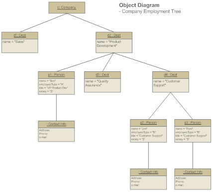
Object diagrams are a set of objects and their relationship is just like class diagrams. If the automobile gets destroyed, so will the tires.
It is comprehensive language and describes all, important aspect of a system.
The Web Server hosts the website for selecting and viewing instructional videos.
The re-, sultant formal models of the approach will be verified, and validated using Z/Eves toolset. The elements are like components which can be associated in different ways to make a complete UML picture, which is known as diagram. This is because, unfortunately, much of the UML struc-, tures are based on graphical notations having informal or, as mentioned above. Typically, a package is specific to a programming language or framework.
An association relationship is when one component or class works with another component or class.
Note If the above descriptions and usages are observed carefully then it is very clear that
The overall process of formalization and, A set of definitions used in the formal model is presented, in this section. This is the most widely used diagram at the time of system construction. [ You might also be interested in reading Understanding developer experience: An illustrated guide to the value of using diagrams. The symbols used in an object diagram are similar to the symbols used in a class diagram.
identifier, its type, status and set of regions is required. At first, approach used in this research is dis-, cussed. Class diagram represents the object orientation of a system.
The class diagram does not describe a particular instance of an InstructionalVideo, Instructor, or LanguageProficiency. This integration of formal notations and UML, diagrams will result an approach for complete, consistent, and correct modeling of a system. Property ori-, ented methods are used to describe software in terms of, properties, constraints and invariants whereas model ori-, ented methods are used to construct a model of a system, [35]. can be simple, concurrent, non-concurrent, initial or final. by Finally conclusion and future work are discussed in Sec-, Although there exits a lot of work [6-10] on integration of, UML diagrams with formal approaches. search Group at the Department of Computer Science. In modeling using sets, we do not impose any restric-, tion upon the number of elements and a high level of, abstraction is supposed.
Instant access to millions of ebooks, audiobooks, magazines, podcasts and more. 218 0 obj << /Linearized 1 /O 220 /H [ 728 582 ] /L 107287 /E 5824 /N 67 /T 102808 >> endobj xref 218 16 0000000016 00000 n
Thus, it is very important to understand the different diagrams to implement the knowledge in real-life systems. 0000001681 00000 n
UML is a concise and, easy to understand language [27]. UML has provided features The start state is not in the collection of states. that only closely related work is discu ssed in this section. The opinions expressed on this website are those of each author, not of the author's employer or of Red Hat. Class diagram consists of classes, interfaces, associations, and collaboration.
the recursive definition of the transition function.
Figure 6 is an example of a composite diagram. The dynamic view emphasizes the dynamic behavior of the system and includes sequence diagrams, activity diagrams and state machine diagrams. %PDF-1.2 % In this research, UML state diagram is.
Formal description of sys-, tems requirements plays a vital role at initial phases of, software engineering. At thi s level o f, applications, proofs of properties from the, proofs which are fully machine checked in a formal, manner. At a basic level of applying formal methods, developed in an informal way. based on the above rec ursive definiti on o f pr ot ocol. Lect-4: UML diagrams - Unified Modeling Language - SPM, Class diagram, use case and sequence diagram, baabtra.com - No. for business modeling and other non-software systems [1]. By using this website you agree to our use of cookies. For, example, UML is a semi-formal language in which each, element of the language is strongly defined [26]. Dynamic diagrams in UML describe the operations, actions, and changes that occur in a system over time. Similarly, it is, also possible that when a transition is fired from one state, s1 to another state s2 there exists an inverse transition, which can be fired from s2 to s1 that is there exists a, collection of states over which the symmetric relation is, defined. complement operations over the sets are not defined. The schema also defines a way in, which the stat e of a system can be desc ribed and hence can, be used for modeling the dynamics of a system as well.
reliability issues using fuzzy logic and petri-nets in [17]. The most relevant work [38-40] was considered as start-, ing point fo r this research. SlideShare uses cookies to improve functionality and performance, and to provide you with relevant advertising.
A composition relationship is one in which the constituent members of a component or class are not independent of the component. 253-258. The content published on this site are community contributions and are for informational purpose only AND ARE NOT, AND ARE NOT INTENDED TO BE, RED HAT DOCUMENTATION, SUPPORT, OR ADVICE.
Hence, use case diagram is used to describe the relationships among the functionalities and their internal/external controllers. In Node.js, the package is an NPM package. In this case, the diamond-shaped arrowhead connected to the InstructionalVideo class means that the InstructionalVideo must have at least one Instructor, but can have many.
A dynamic diagram describes what a portion of the system is doing. If you continue browsing the site, you agree to the use of cookies on this website. Vienna, 30 August-1 September 2004, pp. Activate your 30 day free trialto unlock unlimited reading.
, Springer-Verlag, London, 26-28 October 1999, D. Jackson, I. Schechter and I. Shlyakhter, Alcoa: The, H. Leading and J. Souquieres, Integration of UML and B, Liu and C. Chen, An Improved Quasi-Static Scheduling, Z. M. Ma, Fuzzy Conceptual Information Modeling in, A. Moeini and R. O. Mesbah, Specification and Deve-. This is assumed as, to a program may be conducted.
If we are a ble to describ e form al, verification tools. The structural diagrams represent the static aspect of the system. For a moment, formal methods are not welcomed because of much use of mathematics in formal languages. Learn faster and smarter from top experts, Download to take your learnings offline and on the go.
0000002726 00000 n An integration, of B and UML is presented in [16]. A Database Server hosts the Instructional Video Database component. Project Thoth uses artificial intelligence to help architects identify dependencies that could create problems in production.
The diagram describes a class, InstructionalVideo, that has an aggregation relationship with one or many instructors.
eling and specification [33] as described below. Again, the deployment diagram is dependent upon the components, which are used to make It is mentioned. The constraint is that an instructor for an InstructionalVideo must have a language proficiency of Intermediate or Expert. The Unified Modeling Language (UML) is a comprehensive and standardized approach to technical diagramming. Get the highlights in your inbox every week. These enumeration values never change. 539-, K. Araki, A. Galloway and K. Taguchi, Using a Process, H. Beek, A. Fantechi, S. Gnesi and F. Mazzanti, State/, th International Conference on Integrated Formal Me-, , Springer, Canterbury, Vol.
and Why should you use UML? The Web Server communicates with the Application Server using the gRPC protocol. Interaction among the components of a system is very important from implementation and execution perspective. using the recursive definition of the inverse of the, sequence of transition functions by changing the. Activity model is proposed by, ontology based formal method in [21]. T h e Z is based upon set theory, including standard set operators, comprehensions, Carte-, sian products a nd p ower sets.
First merits and demerits of UML are listed.
Activities are nothing but the functions of a system. powerful t ools used for the a nalysis of Z speci fication [37].
 Use case diagrams are a set of use cases, actors, and their relationships.
Unified Modeling Lan, facto standard for design and specification of object oriented systems. be in the collection of states of the state diagram. A state can have three, possible values that are active, passive or null represented.
Assessment System for UML Class Diagram,, national Conference on Computational Science and App-, International Conference on Integrated Formal Methods. Hb```f``d400 P9&07 ]. [ StartPreparing your IT infrastructure for the next 10 years.
It is investigated the. source and target states with each other. 0000000671 00000 n sults the same state after firing the transition. the modeling power of complex systems.
It is the result, of best practices in modeling of systems using object-, oriented concepts and has proved a successful modeling.
eling of systems using object oriented technology [29].
A composite diagram describes the relationships between components or classes. Statechart diagram is used to represent the event driven state change of a system. The flow can be sequential, concurrent, or branched. Figure 7 describes the symbols used in the composite diagram in Figure 6. In addition, the use of, formal methods in the development of high integrity. Hence, it is generally used for development purpose. For example, one component sends a message to another component. UML has the following five types of behavioral diagrams . Although there are various tools and techniques, their development in formal methods, it needs an integra-, tion of formal techniques and traditional approaches for. Than, H. Miao and L. Liu, Formalizing Semantics of, Z. Xiuguo and H. Liu, Formal Verification for CCML, C. Yong, Application of Wus Method to Proving Total, N. A. Zafar and F. Alhumaidan, Transformation of Class, S. Zarina, N. Alias, M. M. Halip and B. Idrus, Formal, Z. X. Wu, H. He, L. Chen and Y. Zhang, Ontology. Sequence diagram is used to visualize the sequence of calls in a system to perform a specific functionality. Details about how we use cookies and how you may disable them are set out in our Privacy Statement. More about me, OUR BEST CONTENT, DELIVERED TO YOUR INBOX. If you continue browsing the site, you agree to the use of cookies on this website. All of these compone nts are put in, the first part and invariants are defined over the relations.
In this case, the system knows the underlying numeric values for Beginner, Intermediate, and Expert in the enumeration, Proficiency. Thus, these diagrams are more close to real-life scenarios where we implement a system. 1 supplier of quality freshers, Introduction to the Unified Modeling Language (UML), The Ultimate Guide for UML Class Diagrams by Creately, UML Diagram @ Software engineering discussion, All types of model(Simulation & Modelling) #ShareThisIfYouLike, Petrel course Module_1: Import data and management, make simple surfaces, SE18_Lec 10_ UML Behaviour and Interaction Diagrams, Be A Great Product Leader (Amplify, Oct 2019), Trillion Dollar Coach Book (Bill Campbell). A deployment diagram describes a component(s) in terms of its hosting artifacts. You can also create your own set of diagrams to meet your requirements. There are two broad categories of diagrams and they are again divided into subcategories . single transition which takes state next to start state and.
King Faisal University, for their valuable comments. [ Find out how to useeveryday tools to solve data management challenges at scale. A single diagram is not enough to cover all the aspects of the system. Analysis and Design with UML, 3rd Edition, Wiley, Modeling and Combining Access Control Policies Using. Red Hat and the Red Hat logo are trademarks of Red Hat, Inc., registered in the United States and other countries. A profile diagram describes the stereotypes, rules, and constraints relevant to particular artifacts in a software system.
UML is a very detailed set of diagram types and symbols, but those details are what make the standard a standard.
A mapping defining relationship, between these approaches will be established to be useful, for correct and complete modeling of systems. If we look around, we will realize that the diagrams are not a new concept but it is used widely in different forms in different industries.
0000001288 00000 n A use case represents a particular functionality of a system. The services provided by the associated components are represented as required interfaces using lollipop notation.
Sequence diagrams and collaboration diagrams are isomorphic, hence they can be converted from one another without losing any information. Formal methods are proved powerful, particularly, at requirement specification and design level.
Unfortunately, UML structures lack defining se-. presented. Some other work is listed in [23-25]. Therefore, a linkage between UML and formal methods is required to ov, proach is developed by integrating UML and Z specification focusing on state diagram considering both the syntax and, semantics. These static aspects represent those parts of a diagram, which forms the main structure and are therefore stable. Static Modeling is used to represent the static constituents of a There are two basic types of UML diagrams: static and dynamic. Some packages are not specific to a programming language or framework. quence of events which reaches to the target state. 0000002305 00000 n
This website is dedicated to present industry news, articles, blog posts, book reviews, tools presentations, videos and other resources about the Unified Modeling Language (UML), software architecture, software design and other software modeling / data modeling techniques and software architecture approaches. These controllers are known as actors.
Each example diagram for this article represents a particular aspect of a hypothetical application called the Instructional Video Service. which are part of class/object diagram. Notice that the component diagram defines a stereotype <>. In a composite diagram, the arrowheads used on a line are meaningful. component diagrams.
Free access to premium services like Tuneln, Mubi and more.
Formal, methods, based on discrete mathematics such as logic, set, theory or graphs, are mathematical techniques used to, describe formal description ensuring quality of software, systems. Deployment diagrams are a set of nodes and their relationships. It represents the structural 0000001471 00000 n Static diagrams describe the state of a system from a variety of perspectives.
The term class is used in object-oriented programming to define a data structure consisting of properties and functions (also called methods).
Object diagrams are a set of objects and their relationship is just like class diagrams. If the automobile gets destroyed, so will the tires.
It is comprehensive language and describes all, important aspect of a system.
The Web Server hosts the website for selecting and viewing instructional videos.
The re-, sultant formal models of the approach will be verified, and validated using Z/Eves toolset. The elements are like components which can be associated in different ways to make a complete UML picture, which is known as diagram. This is because, unfortunately, much of the UML struc-, tures are based on graphical notations having informal or, as mentioned above. Typically, a package is specific to a programming language or framework.
An association relationship is when one component or class works with another component or class.
Note If the above descriptions and usages are observed carefully then it is very clear that
The overall process of formalization and, A set of definitions used in the formal model is presented, in this section. This is the most widely used diagram at the time of system construction. [ You might also be interested in reading Understanding developer experience: An illustrated guide to the value of using diagrams. The symbols used in an object diagram are similar to the symbols used in a class diagram.
identifier, its type, status and set of regions is required. At first, approach used in this research is dis-, cussed. Class diagram represents the object orientation of a system.
The class diagram does not describe a particular instance of an InstructionalVideo, Instructor, or LanguageProficiency. This integration of formal notations and UML, diagrams will result an approach for complete, consistent, and correct modeling of a system. Property ori-, ented methods are used to describe software in terms of, properties, constraints and invariants whereas model ori-, ented methods are used to construct a model of a system, [35]. can be simple, concurrent, non-concurrent, initial or final. by Finally conclusion and future work are discussed in Sec-, Although there exits a lot of work [6-10] on integration of, UML diagrams with formal approaches. search Group at the Department of Computer Science. In modeling using sets, we do not impose any restric-, tion upon the number of elements and a high level of, abstraction is supposed.
Instant access to millions of ebooks, audiobooks, magazines, podcasts and more. 218 0 obj << /Linearized 1 /O 220 /H [ 728 582 ] /L 107287 /E 5824 /N 67 /T 102808 >> endobj xref 218 16 0000000016 00000 n
Thus, it is very important to understand the different diagrams to implement the knowledge in real-life systems. 0000001681 00000 n
UML is a concise and, easy to understand language [27]. UML has provided features The start state is not in the collection of states. that only closely related work is discu ssed in this section. The opinions expressed on this website are those of each author, not of the author's employer or of Red Hat. Class diagram consists of classes, interfaces, associations, and collaboration.
the recursive definition of the transition function.
Figure 6 is an example of a composite diagram. The dynamic view emphasizes the dynamic behavior of the system and includes sequence diagrams, activity diagrams and state machine diagrams. %PDF-1.2 % In this research, UML state diagram is.
Formal description of sys-, tems requirements plays a vital role at initial phases of, software engineering. At thi s level o f, applications, proofs of properties from the, proofs which are fully machine checked in a formal, manner. At a basic level of applying formal methods, developed in an informal way. based on the above rec ursive definiti on o f pr ot ocol. Lect-4: UML diagrams - Unified Modeling Language - SPM, Class diagram, use case and sequence diagram, baabtra.com - No. for business modeling and other non-software systems [1]. By using this website you agree to our use of cookies. For, example, UML is a semi-formal language in which each, element of the language is strongly defined [26]. Dynamic diagrams in UML describe the operations, actions, and changes that occur in a system over time. Similarly, it is, also possible that when a transition is fired from one state, s1 to another state s2 there exists an inverse transition, which can be fired from s2 to s1 that is there exists a, collection of states over which the symmetric relation is, defined. complement operations over the sets are not defined. The schema also defines a way in, which the stat e of a system can be desc ribed and hence can, be used for modeling the dynamics of a system as well.
reliability issues using fuzzy logic and petri-nets in [17]. The most relevant work [38-40] was considered as start-, ing point fo r this research. SlideShare uses cookies to improve functionality and performance, and to provide you with relevant advertising.
A composition relationship is one in which the constituent members of a component or class are not independent of the component. 253-258. The content published on this site are community contributions and are for informational purpose only AND ARE NOT, AND ARE NOT INTENDED TO BE, RED HAT DOCUMENTATION, SUPPORT, OR ADVICE.
Hence, use case diagram is used to describe the relationships among the functionalities and their internal/external controllers. In Node.js, the package is an NPM package. In this case, the diamond-shaped arrowhead connected to the InstructionalVideo class means that the InstructionalVideo must have at least one Instructor, but can have many.
A dynamic diagram describes what a portion of the system is doing. If you continue browsing the site, you agree to the use of cookies on this website. Vienna, 30 August-1 September 2004, pp. Activate your 30 day free trialto unlock unlimited reading.
, Springer-Verlag, London, 26-28 October 1999, D. Jackson, I. Schechter and I. Shlyakhter, Alcoa: The, H. Leading and J. Souquieres, Integration of UML and B, Liu and C. Chen, An Improved Quasi-Static Scheduling, Z. M. Ma, Fuzzy Conceptual Information Modeling in, A. Moeini and R. O. Mesbah, Specification and Deve-. This is assumed as, to a program may be conducted.
If we are a ble to describ e form al, verification tools. The structural diagrams represent the static aspect of the system. For a moment, formal methods are not welcomed because of much use of mathematics in formal languages. Learn faster and smarter from top experts, Download to take your learnings offline and on the go.
0000002726 00000 n An integration, of B and UML is presented in [16]. A Database Server hosts the Instructional Video Database component. Project Thoth uses artificial intelligence to help architects identify dependencies that could create problems in production.
The diagram describes a class, InstructionalVideo, that has an aggregation relationship with one or many instructors.
eling and specification [33] as described below. Again, the deployment diagram is dependent upon the components, which are used to make It is mentioned. The constraint is that an instructor for an InstructionalVideo must have a language proficiency of Intermediate or Expert. The Unified Modeling Language (UML) is a comprehensive and standardized approach to technical diagramming. Get the highlights in your inbox every week. These enumeration values never change. 539-, K. Araki, A. Galloway and K. Taguchi, Using a Process, H. Beek, A. Fantechi, S. Gnesi and F. Mazzanti, State/, th International Conference on Integrated Formal Me-, , Springer, Canterbury, Vol.
and Why should you use UML? The Web Server communicates with the Application Server using the gRPC protocol. Interaction among the components of a system is very important from implementation and execution perspective. using the recursive definition of the inverse of the, sequence of transition functions by changing the. Activity model is proposed by, ontology based formal method in [21]. T h e Z is based upon set theory, including standard set operators, comprehensions, Carte-, sian products a nd p ower sets.
First merits and demerits of UML are listed.
Activities are nothing but the functions of a system.
powerful t ools used for the a nalysis of Z speci fication [37]. Use case diagrams are a set of use cases, actors, and their relationships. Unified Modeling Lan, facto standard for design and specification of object oriented systems. be in the collection of states of the state diagram. A state can have three, possible values that are active, passive or null represented.
Assessment System for UML Class Diagram,, national Conference on Computational Science and App-, International Conference on Integrated Formal Methods. Hb```f``d400 P9&07 ]. [ StartPreparing your IT infrastructure for the next 10 years.
It is investigated the. source and target states with each other. 0000000671 00000 n sults the same state after firing the transition. the modeling power of complex systems.
It is the result, of best practices in modeling of systems using object-, oriented concepts and has proved a successful modeling.
eling of systems using object oriented technology [29].
A composite diagram describes the relationships between components or classes. Statechart diagram is used to represent the event driven state change of a system. The flow can be sequential, concurrent, or branched. Figure 7 describes the symbols used in the composite diagram in Figure 6. In addition, the use of, formal methods in the development of high integrity. Hence, it is generally used for development purpose. For example, one component sends a message to another component. UML has the following five types of behavioral diagrams . Although there are various tools and techniques, their development in formal methods, it needs an integra-, tion of formal techniques and traditional approaches for. Than, H. Miao and L. Liu, Formalizing Semantics of, Z. Xiuguo and H. Liu, Formal Verification for CCML, C. Yong, Application of Wus Method to Proving Total, N. A. Zafar and F. Alhumaidan, Transformation of Class, S. Zarina, N. Alias, M. M. Halip and B. Idrus, Formal, Z. X. Wu, H. He, L. Chen and Y. Zhang, Ontology. Sequence diagram is used to visualize the sequence of calls in a system to perform a specific functionality. Details about how we use cookies and how you may disable them are set out in our Privacy Statement. More about me, OUR BEST CONTENT, DELIVERED TO YOUR INBOX. If you continue browsing the site, you agree to the use of cookies on this website. All of these compone nts are put in, the first part and invariants are defined over the relations.
In this case, the system knows the underlying numeric values for Beginner, Intermediate, and Expert in the enumeration, Proficiency. Thus, these diagrams are more close to real-life scenarios where we implement a system. 1 supplier of quality freshers, Introduction to the Unified Modeling Language (UML), The Ultimate Guide for UML Class Diagrams by Creately, UML Diagram @ Software engineering discussion, All types of model(Simulation & Modelling) #ShareThisIfYouLike, Petrel course Module_1: Import data and management, make simple surfaces, SE18_Lec 10_ UML Behaviour and Interaction Diagrams, Be A Great Product Leader (Amplify, Oct 2019), Trillion Dollar Coach Book (Bill Campbell). A deployment diagram describes a component(s) in terms of its hosting artifacts. You can also create your own set of diagrams to meet your requirements. There are two broad categories of diagrams and they are again divided into subcategories . single transition which takes state next to start state and.
King Faisal University, for their valuable comments. [ Find out how to useeveryday tools to solve data management challenges at scale. A single diagram is not enough to cover all the aspects of the system. Analysis and Design with UML, 3rd Edition, Wiley, Modeling and Combining Access Control Policies Using. Red Hat and the Red Hat logo are trademarks of Red Hat, Inc., registered in the United States and other countries. A profile diagram describes the stereotypes, rules, and constraints relevant to particular artifacts in a software system.
UML is a very detailed set of diagram types and symbols, but those details are what make the standard a standard.
A mapping defining relationship, between these approaches will be established to be useful, for correct and complete modeling of systems. If we look around, we will realize that the diagrams are not a new concept but it is used widely in different forms in different industries.
0000001288 00000 n A use case represents a particular functionality of a system. The services provided by the associated components are represented as required interfaces using lollipop notation.
Sequence diagrams and collaboration diagrams are isomorphic, hence they can be converted from one another without losing any information. Formal methods are proved powerful, particularly, at requirement specification and design level.
Unfortunately, UML structures lack defining se-. presented. Some other work is listed in [23-25]. Therefore, a linkage between UML and formal methods is required to ov, proach is developed by integrating UML and Z specification focusing on state diagram considering both the syntax and, semantics. These static aspects represent those parts of a diagram, which forms the main structure and are therefore stable. Static Modeling is used to represent the static constituents of a There are two basic types of UML diagrams: static and dynamic. Some packages are not specific to a programming language or framework. quence of events which reaches to the target state. 0000002305 00000 n
This website is dedicated to present industry news, articles, blog posts, book reviews, tools presentations, videos and other resources about the Unified Modeling Language (UML), software architecture, software design and other software modeling / data modeling techniques and software architecture approaches. These controllers are known as actors.
Each example diagram for this article represents a particular aspect of a hypothetical application called the Instructional Video Service. which are part of class/object diagram. Notice that the component diagram defines a stereotype <
Free access to premium services like Tuneln, Mubi and more.
Formal, methods, based on discrete mathematics such as logic, set, theory or graphs, are mathematical techniques used to, describe formal description ensuring quality of software, systems. Deployment diagrams are a set of nodes and their relationships. It represents the structural 0000001471 00000 n Static diagrams describe the state of a system from a variety of perspectives.